MCE 484 Controls Lab Final Project – Spring 2013
Creating a Flow and Temperature Control System
Welcome to our website dedicated to our class’ MCE 484 final project – creating a system for temperature and flow control for a sink faucet.
Please navigate the links at the top to follow the procedures followed by the students for this project. Results and conclusions for each section of the project, if applicable, are located at the end of the respective section.
Any questions, comments, or concerns can be directed towards our class instructor, Hanz Richter at h.richter@csuohio.edu .
Overall System Description
Group Members: Ibrahim Albibi, Saud Alsaud, Jamal Chehab, Aaron Morris
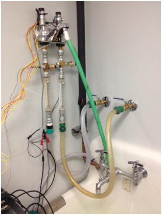
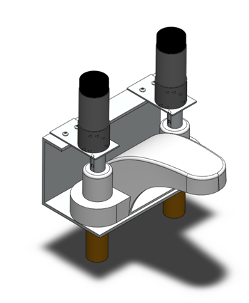
The system layout to control the flow and temperature of the system, utilized numerous pieces of instrumentation, hardware and data acquisition. The system’s goal was to take a hot water source and cold water source, each with a defined temperature and flow and combine the two water sources with control over the combined water temperature and flow rate. This was accomplished by rigging a water faucet up to the domestic hot and cold water lines of the building and using the valving of the faucet to mix the two water sources into a single outlet to be analyzed. The faucet handles were removed and were replaced by DC electric motors with internal encoders connected to the faucet with custom couplings. The DC electric motors were controlled by a WinConn interface that utilized the system’s pressure and temperature. The temperature of the cold water source was gauged by a thermocouple while the hot water source used an RTD (resistance temperature detectors). The pressure of each source was gauged by a pressure transducer attached to each line. Both of these devices sent electronic signals to the WinConn interface in real time, which were calibrated for the system specifically, to determine how much to turn the faucet valves to let an amount of flow. The flow of each water line was gauged by an in-line flow meter attached to each water source but because the flow meters did not give off an electronic reading, they could not be used to control the system easily in real time. The data tables below describe the detailed information of the hardware utilized in the system.
Pressure Transducers with 100 mV Bridge Output
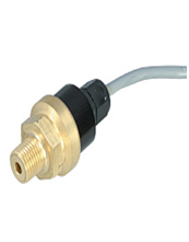
• Output: 0 to 50 mV for 0-1 psi, 0 to 100 mV all other ranges; Bridge Output
• Load Resistance: 50,000 Ohms minimum
• Accuracy: 0.3% BFSL maximum (includes linearity, hysteresis,
and repeatability)
• Operating Temperature:-40 to 80°C (-40 to 176°F)
• Compensated Temperature:-25 to 75°C (-13 to 167°F)
• Process Temperature:-40 to 100°C (-40 to 212°F)
• Thermal Zero Effect: 2% FS maximum over compensated temperature range
• Thermal Span Effect: 2% FS maximum over compensated temperature range
• 1 Year Stability: <0.25% FS
• Proof Pressure: 2x FS (750 psig for 500 psig range)
• Burst Pressure: 3x FS or 750 psig, whichever is less
• Wetted Parts: brass, borosilcate, silicon, RTV, and epoxy
• Vibration: 10 g, 55 to 2000 Hz
• Shock: 30 g
• Process Connection: 1/8 NPT male
• Electrical Connection: 0.4 m (18″) 24 AWG cable
• Weight: 142 grams (5 oz)
In-line Flow meters
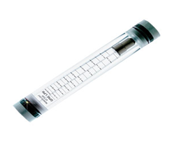
• Accuracy: ±5%
• Meter Body: Acrylic
• O-Ring Material: FKM
• Float: 316 SS (PVC for FL46302)
• Temperature Limit: 65°C (150°F) at 0 psig
• Pressure Limit: 150 psig at 21°C (70°F)
• Pressure Drop: 2 psi max
• Dimensions:FL46307-09: 279 H x 32 mm D (11 x 11.4″)
• Weight: 680 g (1.5 lb)
Omega Thermocouple
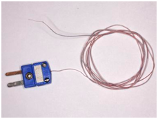
• Thermocouple Type: J
• Part No: IRCO-015
• Wire Size: 0.015” dia.
• Max Service Temp: 371°C (700°F)
• Still Air Response Time: 0.02 sec
• Still H2O Response Time: 0.005 sec
The EMG30 Encoder, Motor, Gearbox 30:1
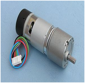
• Rated voltage • 12v
• Rated torque • 1.5kg/cm
• Rated speed • 170rpm
• Rated current • 530mA
• No load speed • 216
• No load current • 150mA
• Stall Current • 2.5A
• Rated output • 4.22W
• Encoder counts per output shaft turn • 360
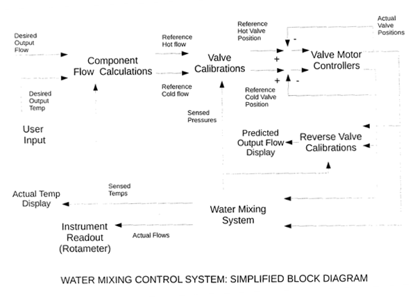
The WinConn control system utilizes a Simulink model to control the flow and temperature of the system. The user prescribes a desired flow rate and temperature of the water, the solver then uses those values to calculate the necessary flow needed from each water source to obtain the overall temperature and flow rate. Those required flow rates are then applied to the valving calculations to determine the motor’s degree of turn on each water source valve. The system the motor’s internal encoder to read the amount the motor’s shaft turns and uses real time feedback and PID control to turn the motor’s shaft just the right amount without too much overshoot. As the motor’s are controlling the valves, the thermocouples and pressure transducers are giving real time data to the system so that if the temperature or pressure changes in either of the water mains suddenly, the system can react and change the angle of shaft rotation to adjust the flow rate of the water mains to match the desired combine temperature and flow rate. The flow chart below visually describes this process.