
Drivetrain Rotordynamics for Vibration Health Monitoring of Gear Tooth Surface Fatigue
RoMaDyC » Areas of Research » Structural Health Monitoring
Health monitoring systems have been installed on rotorcraft for many years. The main purpose of such systems is to predict impending equipment failure for condition based maintenance. Rotorcraft health monitoring systems usually consist of a main computer for data processing and acquisition of in-flight data from accelerometers and tachometers installed on critical components. Components that are monitored include the main and tail rotors, their gear boxes and drivetrains. Vibration data is typically downloaded by a mechanic post flight. The main function is to collect data for identification of normal and abnormal changes in vibration levels on critical components.
Typically, all drivetrain gear sets are monitored by rotorcraft health monitoring systems. A variety of signal processing algorithms called Condition Indicators (CIs) have been developed to detect incipient faults in the gear sets. The vibration CI is a statistical measurement of vibration energy and is calculated using the conditioned signals from accelerometer(s) located on the gearbox. The vibration CI has evolved over the years to become a reliable detector of incipient damage.
Testing is currently being conducted using the NASA Glenn Research Center (GRC) spiral bevel gear test rig to further understand and evaluate the sideband index CI. The test rig is designed with a closed-loop arrangement in which the load is locked into the loop via a split shaft. Driveline rotation is provided by the drive motor through a v-belt connection to an axially stationary helical gear. Torque is created by way of a thrust piston that forces the floating helical gear into mesh. The left side spiral bevel gear set is operated in the normal speed reducer mode where the pinion drives the gear. In contrast, the right side gear set acts as a speed increases. However the gear sets on both the test and slave sides (right and left) of the rig operate in normal contact with the concave side of the pinion in contact with the convex side of the gear. An inline torque meter is used to monitor the load of the test side gear output shaft.
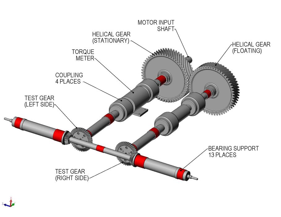
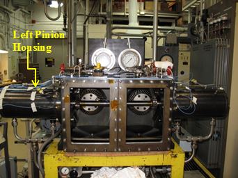
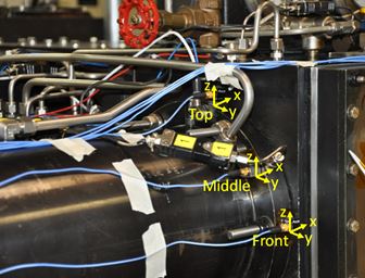
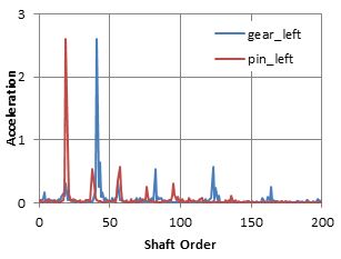
The test rig allows for two sets of spiral bevel gears to be tested at one time. Each side of the test rig (left and right) is equipped with an accelerometer mounted on the respective pinion housing and a keyphasor transducer to generate a once-per-revolution pulse. The once-per-revolution pulse is used for developing the time synchronous average vibration acceleration signal.
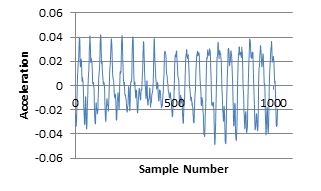
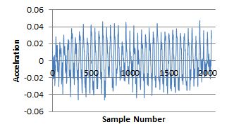
The vibration signal sensed by the accelerometer is conditioned using a technique called time synchronous average (TSA). TSA is used to separate the source signal from extraneous signals, or noise. A once per revolution pulse synched to the pinion shaft rotation is used to establish the periodicity for extraction of the waveforms of interest. The extracted waveforms are then averaged over many revolutions of the pinion shaft to obtain the TSA.
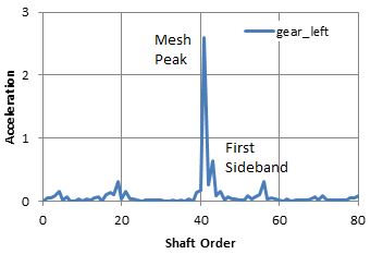
Tests indicate that the sideband index condition indicator is superior to other vibration indicators for monitoring gear tooth damage. The sideband index tracks the magnitudes of the acceleration sidebands about the mesh frequency. As damage initiates on one tooth and then progresses to adjacent teeth, the damage generated signal (once-per-revolution) modulates the mesh signal. The modulation is indicated by sidebands about the mesh frequency, and harmonics thereof, and increases in magnitude with damage. Tests further indicate that the first sideband is the best indicator of damage. However, this conclusion is not completely understood. Modeling of the physical processes responsible for the modulation sidebands is needed for a better understanding and evaluation of the sideband index as a CI for component health monitoring.
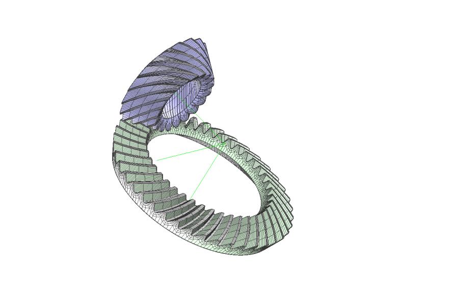
In order to model the modulation of the mesh signal, a rotordynamic analysis accounting for the transmission error variation over the mesh cycle is being developed. In addition to transmission error variation, the rotordynamic analysis being developed will account for variations in gear mesh point, line of action, and mesh stiffness during the mesh cycle. The time varying mesh point, line of action, and mesh stiffness are obtained from a loaded tooth contact analysis (LTCA) performed for increments of pinion roll angle.
Since the vibration signal sensed by the accelerometer is a combination of forcing function effects (gear mesh dynamics, rotordynamics, bearing/rotor interaction, etc.) and transfer function effects (the structural transfer path) the rotordynamic analysis will also include transmission path models developed by a rig modal analysis performed earlier in the test program.