Structural Change Quantification in Rotor Systems
RoMaDyC » Areas of Research » Structural Health Monitoring
A structural change quantification methodology is demonstrated in which the magnitude and location of a structural alteration is identified experimentally in a rotor system. The term structural change is used because it is the most general description of any fault that will alter the rotor’s structural dynamics. Structural change can take the form of shaft damage, component looseness, debris deposition, damaged bearing, etc. The resonance and antiresonance frequencies are captured from multiple frequency response functions and are compared with baseline data to extract frequency shifts due to these features.
The resulting expression contains sufficient information to identify the dynamic characteristics of the rotor in both the frequency and spatial domains. A finite element model with carefully selected tunable parameters is iteratively adjusted using a numerical optimization algorithm to determine the source of the structural change. The methodology is experimentally demonstrated on a test rig with a laterally damaged rotor and the frequency response functions are acquired through utilization of magnetic actuators positioned near the ball bearings.
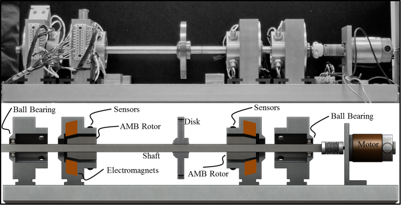
The nominal FE rotor model is initially updated to match the experimental sine sweep data acquired on the baseline (structurally unchanged) rotor test rig.
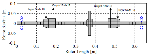
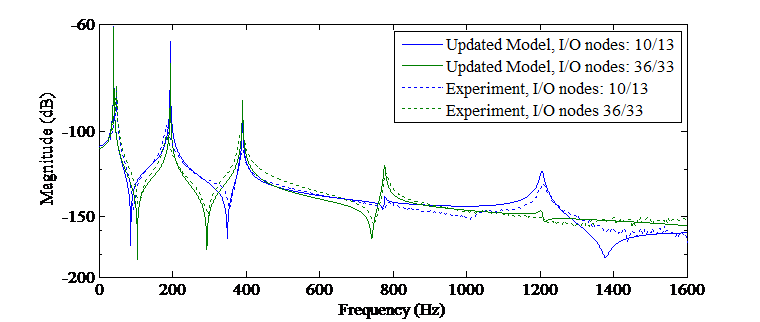
Once the baseline FE rotor model accurately represents the baseline test rig, structural changes are applied. The structural change is achieved by creating a 360 degree circumferential cut at a specific axial location on the shaft to sequentially achieve cases of approximately 25%, 50%, and 75% stiffness reduction in that local region. Of course this type of modification does not represent a realistic fault found in turbomachinery, however, it was a structural change that was possible to simulate with the available rotordynamic code.
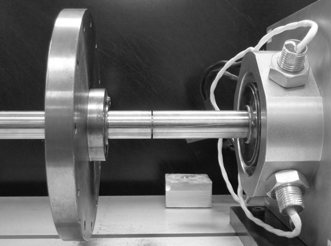
For each stiffness reduction case, sine sweep data is acquired in the nonrotating state and a new set of resonance and antiresonance frequencies were extracted.
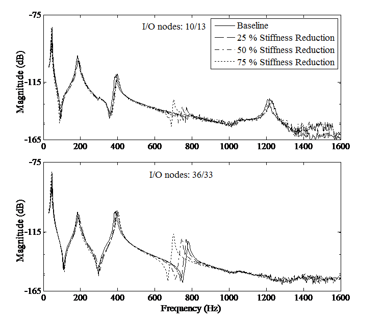
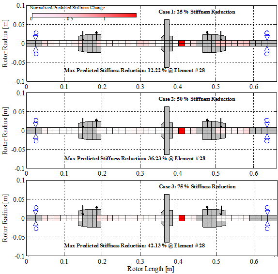
Next, the existing corrected baseline FE rotor model is updated to match each of the structurally altered data sets, engaging a search for a finite element (representing a local region in the shaft) which is responsible for the structural change. Utilization of both resonance and antiresonance frequencies forces the objective function to find a solution, which in this case, is the location and magnitude of the structurally altered shaft region. All three cases correctly located the region of the test rig’s shaft where the circumferential cut was made, however, the magnitude was under predicted in all cases.
